


Building your own development board has clear steps. First, decide what you need. Next, choose the right parts. Then, design the schematic and PCB. After that, put the board together and test it. Careful planning helps you avoid mistakes. You might forget to review your design or use the wrong PCB trace widths. Look at other boards to learn good ideas. Try to keep your design simple. Check your work often with design rule checks. Use decoupling capacitors to keep voltage steady. Good planning saves you time and money.
Requirements and Planning
Design Specifications
You should start by writing down what you want your board to do. Think about the main purpose. Do you want to control lights, read sensors, or connect to the internet? Make a list of features you need. For example, you might need a certain number of digital or analog pins, or support for communication like I2C, UART, or SPI. Check the processing power and memory size you need. If you want to use a special programming language or operating system, make sure your board can support it. Look for boards that work with popular IDEs and have good documentation. A strong community can help you solve problems and find tutorials. Also, think about power use, especially if you want to run your board on batteries.
Tip: Write down your project's needs before you pick parts. This helps you avoid choosing a microcontroller that is too weak or too powerful for your project.
Block Diagram
A block diagram helps you see how everything connects. Draw a box for each main part, like the microcontroller, power supply, and sensors. Use lines to show how these parts connect. Label each line with the type of connection, such as SPI or UART. Show the voltage levels for each part. If some parts use different voltages, add a note for level shifters. This diagram makes it easier to spot missing parts or problems before you start building.
- Draw a block for each main function.
- Connect the blocks with lines to show how they talk to each other.
- Label the lines with the communication protocol.
- Mark the voltage for each block.
- Add level shifters if needed.
Studying Existing Boards
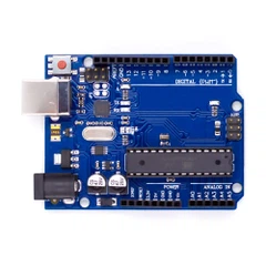
You can learn a lot by looking at popular boards. Many people use boards like the Arduino Uno, Blue Pill, NodeMCU, and ESP32-DevKitC. These boards show good ways to lay out parts and connect them. Companies like NXP make many reference boards for different uses, from simple projects to advanced ones. When you study these boards, check how they handle power, what connectors they use, and how they make programming easy. This research helps you avoid common mistakes and gives you ideas for your own design.
Note: Reviewing proven designs saves you time and helps you build a board that works well.
If you plan carefully and learn from others, you will build a better board. Start your project today and join online communities to get even more tips and support!
Component Selection
Microcontroller Choice
You must pick the right microcontroller for your project. Think about what you want your board to do. Some projects only need simple control. Others need fast processing or real-time work. You can pick from 8-bit, 16-bit, or 32-bit microcontrollers. Each type has its own speed and features.
Here are some things to think about when you pick a microcontroller:
- Application complexity: Simple jobs need less power. Harder projects need more speed and memory.
- Performance and architecture: 8-bit chips are good for easy jobs. 32-bit chips are better for hard tasks.
- Power use: If you use batteries, pick chips that save energy.
- Community support: Popular chips like Arduino, STM32, and ESP32 have lots of help online.
- Connectivity: Some microcontrollers have Wi-Fi, Bluetooth, or Ethernet built in.
- Memory: Make sure you have enough Flash and RAM for your code and data.
- Tools and IDEs: Check if you can use easy software like Arduino IDE or more advanced tools.
- Do not pick a chip that is too weak or too strong. If your chip has too few features, you may need to redesign your board later. If it has too many features, you might waste money and power. Try to match your needs with the right microcontroller.
Many people use these microcontrollers for DIY projects:
1.8051 microcontrollers
2.AVR microcontrollers
3.PIC microcontrollers
4.TI MSP430
5.Arduino
6.STM32
7.ESP8266 and ESP32
8.NodeMCU
These chips have many guides and examples. You can find lots of help for your board.
Tip: Pick a microcontroller that fits your project and has good support. This makes building and fixing problems much easier.
Development Board Components
A good development board needs more than just a microcontroller. You need other parts to make it work well and connect to other devices. Here is a table of important components and what they do:
| Component | Description |
|---|---|
| Processor Core (CPU) | Runs your code and controls the board. |
| Memory | Stores your program and data (Flash, RAM, EEPROM). |
| Interrupt Controller | Lets the chip respond quickly to events. |
| Timer / Counter | Measures time and counts events. |
| Digital I/O | Lets you connect buttons, LEDs, and other digital devices. |
| Analog I/O | Reads signals from sensors (like temperature or light). |
| Communication Interfaces | Connects to other devices using UART, SPI, I2C, or USB. |
| Debugging Unit | Helps you find and fix problems in your code. |
| Power Management | Keeps the voltage steady and safe for the chip. |
You also need these parts for a basic board:
- I/O Pins: Connect to sensors, motors, and other devices.
- Communication Ports: Use UART, SPI, or I2C to talk to other chips.
- USB Interface: Lets you program and debug your board.
- Reset Button: Restarts the microcontroller if it gets stuck.
- Connectors: Make it easy to plug in wires or modules.
- LEDs & Buttons: Help you test and control your board.
- Crystal Oscillator: Gives the chip a clock signal to keep time.
Note: Always add decoupling capacitors near the microcontroller. They help keep the voltage steady and stop noise.
Power Supply Options
Your development board needs a safe and steady power supply. You have several choices. Each one has its own benefits. Here is a table to help you decide:
| Power Supply Option | Description | Advantages |
|---|---|---|
| USB Power | Use a USB cable to get 5V power. Good for programming and running the board. | Easy to use, stable power, works with most computers. |
| 5V or 3.3V Power Pins | Connect a regulated voltage directly to the board. | Simple, works if you have a good power source. |
| Vin or RAW Pin | Use a higher voltage (6V-12V) and let the board's regulator lower it. | Handles power loss in wires, powers more devices, very stable. |
If you want to use batteries, make sure your voltage regulator can handle the battery voltage. Always check the microcontroller's voltage range before you connect power.
USB to Serial Converter
You need a way to program your board and talk to your computer. A USB to serial converter does this job. The FTDI FT232RL chip is the most reliable for this. It works with many operating systems and has built-in protection. Many people use SparkFun's FTDI Basic board, which uses this chip. The Beefy 3 board uses the newer FT231X chip and gives more power for your board.
Other good choices include:
1.CH340G (cheap and works well)
2.Silicon Labs CP2102 (simple and dependable)
3.Microchip MCP2200 (has extra features)
4.Exar XR21V1410 (very fast and reliable)
5.If you want the best results, use FTDI chips. They work with most boards and have lots of support.
Peripheral Modules
Peripheral modules add extra features to your board. You can connect sensors, displays, or wireless modules. Here are some common modules found on popular boards:
| Development Board | Common Peripheral Modules Integrated |
|---|---|
| Arduino Uno | GPIO pins, ADC, PWM outputs |
| ESP32 | GPIO pins, ADC, PWM, Wi-Fi, Bluetooth |
| STM32 Nucleo | GPIO pins, analog inputs, PWM, UART, SPI, I2C |
| Teensy 4.1 | Digital and analog I/O, ADC, PWM |
| Adafruit Feather M4 | GPIO pins, PWM outputs |
These modules let you build things like robots, smart home devices, and IoT gadgets. You can start simple and add more modules as you learn.
Tip: Start with a simple design. Add only the parts you need. This makes your board easier to build and fix. You can always add more features later.
You can find most parts online or at electronics stores. Look for parts with good reviews and lots of guides. This will help you finish your board faster and with fewer problems.
Ready to build your own development board? Pick your parts carefully, keep your design simple, and have fun. Every project helps you learn new skills and brings you closer to building amazing things!
Schematic and PCB Design

Designing your schematic and PCB is a key step in building a reliable development board. Careful planning and the right tools help you avoid mistakes and make your board easier to assemble and debug.
Schematic Design
You start by drawing a detailed schematic. This is like a map that shows how every part connects. Software like KiCAD makes this job easier. You can pick parts from built-in libraries or use community-made symbols for popular microcontrollers. If you cannot find a part, you can create your own symbol and footprint. This helps you match the real part exactly.
Follow these steps for a strong schematic:
1.Place all components on the grid. Use shortcuts like 'A' to add symbols and 'R' to rotate them.
2.Choose parts that fit your needs. For high-speed circuits, pick low-ESR capacitors and chips with the right frequency ratings.
3.Put decoupling capacitors close to the power pins of your microcontroller. This reduces noise and keeps your board stable.
4.Connect everything with the 'Add Wire' tool. Make sure each wire goes to the right place.
5.For special signals, like differential pairs, keep the wires the same length and spacing.
6.Build a strong power network. Add power and ground symbols and connect them well.
7.Use the annotation tool to give each part a unique name. This makes it easy to find parts later.
8.Run the Electrical Rule Check (ERC). This tool finds mistakes like missing wires or unconnected pins.
9.Create a Bill of Materials (BOM) and a netlist. These help you order parts and move to PCB layout.
Tip: Use existing symbol and footprint libraries for your microcontroller. This saves time and reduces errors.
Some designers use special methods to show connectors and daughterboards. For example, you can use receptacle connectors or direct module symbols. Each method has pros and cons, like better 3D views or easier BOM management. You can even assign more than one 3D model to a footprint for better visualization.
PCB Layout
Once your schematic is ready, you move to PCB layout. This step turns your circuit map into a real board. Good layout makes your development board work better and last longer.
Here are some best practices for PCB layout:
1.Place decoupling capacitors as close as possible to the microcontroller pins.
2.Keep power and ground planes solid and unbroken. This reduces noise and improves power delivery.
3.Avoid putting parts too close to the edge or to each other. This makes assembly easier and lowers production costs.
4.Check your manufacturer's rules for trace width, spacing, and via size. This helps you avoid problems during production.
5.Route high-speed or sensitive signals with short, direct traces.
6.Separate analog and digital sections to reduce interference.
7.Common mistakes include ignoring power and ground planes, placing parts poorly, and not thinking about how the board will be made. These 8.mistakes can cause noise, signal problems, and even make your board fail.
Note: Always review your layout against proven designs. Boards like Arduino and STM32 Nucleo show good ways to place parts and route signals.
Signal Integrity
Signal integrity means your signals travel cleanly without noise or loss. You need to plan for this, especially if your board uses both analog and digital parts.
Follow these guidelines for strong signal integrity:
1.Keep analog and digital circuits apart. Place them in different areas of the board.
2.Use separate ground planes for analog (AGND) and digital (DGND) signals. Connect them at a single star point.
3.Make traces for clocks and high-speed signals as short as possible.
4.Match the length and spacing of differential pairs.
5.Use wide traces for power and ground to lower resistance.
6.Space out signal traces to reduce crosstalk.
7.Shield sensitive areas and keep return paths continuous.
8.Avoid ground loops by using a single-point ground reference.
9.Testing your board with tools like multimeters and logic analyzers helps you catch problems early. Good grounding and careful layout keep your development board running smoothly.
Simulation and Prototyping
Before you order your PCB, you should test your design. Simulation and prototyping help you find mistakes and fix them early.
You can use breadboards or proto-boards to build a simple version of your circuit. This lets you check if everything works before you spend money on a real PCB. Many people start with a development board or kit to test their code and hardware.
Simulation tools make this process even better. Programs like LTSpice, MultiSim Live, CircuitMaker, EasyEDA, and Circuit Lab let you test your circuit on your computer. You can see how signals move and find problems without building anything. Some tools, like Autodesk Fusion 360, even show your PCB in 3D. This helps you check if parts fit and if the layout makes sense.
Tip: Always simulate and prototype before making your final PCB. This saves time, money, and frustration.
When you finish your design, use your CAD tool to create Gerber files. These files tell the manufacturer how to make your board. Double-check everything before you send your files.
Building your own development board takes careful design and testing. Each step, from schematic to simulation, helps you make a board that works well and is easy to use. Start your design today and see how much you can learn and create!
Assembly and Testing

Soldering Components
You must put your development board together carefully. First, place each part in the right spot on the PCB. Most parts use soft soldering. This melts a tin-lead mix to join small parts. For SMT parts, reflow soldering is better. You put on solder paste, add the parts, then heat the board in a reflow oven. Through-hole parts often use wave soldering. A wave of melted solder connects the pins. If you have special or sensitive parts, try selective or intrusive soldering. Always pick the right flux core solder, like rosin or no-clean flux. This helps stop residue and makes the solder joints better.
Tip: Look out for problems like cold joints, solder bridges, or parts in the wrong place. These can make your board not work.
Power and Functionality Checks
After you build your board, check it before turning it on. Do these steps:
- Use a multimeter to check all power rails and voltages.
- Look for short circuits or solder bridges.
- Turn on the board and make sure the voltage is within ±5% of the target.
- Use test points on the PCB to make checking easier.
- Program the microcontroller with in-system programming (ISP).
- Test simple things like LEDs, buttons, and ports.
- Write down each test and what happened. This helps you find and fix problems fast.
Programming the Development Board
You can program your board with popular tools. Arduino IDE is easy and has lots of help online. STM32CubeIDE and STM32CubeMX are good for STM32 boards. Raspberry Pi Pico boards work with MicroPython and C/C++. Many boards use USB or JTAG for programming and debugging. Pick the tool that matches your microcontroller and what you know.
| Board Type | Programming Environment | Best For |
|---|---|---|
| Arduino Uno | Arduino IDE | Beginners, IoT |
| STM32 Nucleo | STM32CubeIDE, ST-Link | Advanced development |
| Raspberry Pi Pico | MicroPython, C/C++ | Learning, smart gadgets |
Debugging
Debugging helps you find and fix mistakes. Use tools like in-circuit debuggers (ICDs), JTAG, or ST-LINK. These let you set breakpoints, watch variables, and step through code. IDEs like STM32CubeIDE and Keil have features like real-time variable tracking and memory checks. You can also use logic analyzers and oscilloscopes to look at signals. Add debug messages to your code to see what happens during tests. Always check for things like wrong register settings, memory mistakes, or bad solder joints.
Note: Careful debugging and testing make your development board strong and ready for real use.
Building and testing your own board teaches you important skills. Each step helps you get closer to making your own electronics. Start your project now and join the maker community to share what you make!
You now know how to plan, pick parts, design, build, and test your board. Experts say to begin with easy steps and use a block diagram. Pick your parts with care. You can get help in forums like Arm Community, E2E, EDAboard, and Electro-Tech-Online.
Look at guides, watch webinars, and take courses to learn more.
Makers use AI, IoT, and open-source tools in their projects today.
Keep your design easy and learn from others. Try new things, show your work, and join online groups to become a better maker.
FAQ
What tools do you need to design a PCB?
You need PCB design software like KiCAD or EasyEDA. Over 70% of hobbyists use KiCAD for free and open-source projects. You also need a multimeter and soldering iron for assembly.
Tip: Start with free tools to learn faster.
How much does it cost to build a basic development board?
Most DIY boards cost $10–$30 for parts. If you order a custom PCB, expect $5–$20 per board. Shipping and assembly can add $10. Over 80% of makers keep costs under $50.
| Item | Typical Cost |
|---|---|
| Microcontroller | $2–$8 |
| PCB | $5–$20 |
| Other Parts | $5–$15 |
Can you reuse parts from old electronics?
Yes, you can reuse components like resistors, capacitors, and connectors. Over 60% of makers salvage parts to save money and reduce waste. Always test reused parts before using them.
How do you test if your board works?
You check voltages with a multimeter. You upload a simple program to blink an LED. Over 90% of makers use this method for first tests. If the LED blinks, your board works.
// Simple LED blink test digitalWrite(LED_BUILTIN, HIGH); delay(500); digitalWrite(LED_BUILTIN, LOW); delay(500);
Where can you get help if you have problems?
You can join forums like EEVblog, Electro-Tech-Online, and Arduino. Over 75% of beginners solve problems by asking questions online. You find guides, videos, and community support.
Ready to build your own board? Start today and join thousands of makers sharing ideas and success stories!