


How does arduino car kit work?
You connect wires, upload code, flip a switch - and nothing happens. Or worse: your car spins in circles, constantly veers left, or moves for three seconds before dying. Sound familiar?
Here's what most Arduino car tutorials won't tell you: the magic isn't in the kit itself - it's in understanding the signal chain that turns digital commands into physical motion. When I first built an Arduino car, I spent two frustrating hours troubleshooting why one wheel spun faster than the other. The answer? A 2V voltage drop I didn't know existed. That detail wasn't in any product description.
Arduino car kits work through a three-layer architecture: the Arduino microcontroller acts as the brain making decisions, the motor driver translates those decisions into electrical signals strong enough to power motors, and DC motors convert that electrical energy into rotation. Think of it like a chain of command: your code gives orders (Arduino), a translator amplifies the message (motor driver), and workers execute the task (motors). Break any link, and the entire system fails.
The Signal Journey: From Code to Movement
Watch an Arduino car move, and you're witnessing an intricate dance between software and hardware happening thousands of times per second.
Arduino: The Decision Maker
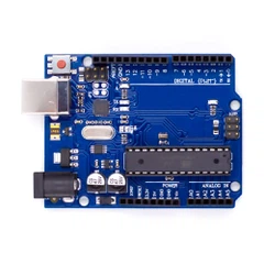
The Arduino microcontroller - typically an UNO R3 - sits at the heart of every car kit. This 16MHz processor runs your uploaded code in a continuous loop, reading sensor inputs and sending commands to connected components through its 14 digital pins and 6 analog pins.
When you write digitalWrite(motorPin, HIGH), here's what actually happens: The Arduino's ATmega328P chip switches that pin from 0V to 5V in roughly 62.5 nanoseconds. This voltage change creates a digital signal - essentially a very fast on/off switch. But here's the catch: Arduino pins can only safely provide 20-40 milliamps (mA) of current. A typical DC motor needs 200-500mA. Connecting a motor directly to an Arduino pin would be like asking a garden hose to fill an Olympic pool - the hardware will overload and potentially fry.
The Arduino compatible market reached $815.3 million in 2025 and is projected to grow to $1,598.9 million by 2032, driven largely by educational adoption. Yet most beginners don't understand this current limitation until after damaging their first board.
Motor Driver: The Power Amplifier
This is where the L298N motor driver enters - and where most confusion begins. The L298N acts as a controllable gateway between your low-power Arduino signals and your high-power motor circuits. It uses H-bridge circuitry, which sounds complex but works on a beautifully simple principle.
H-Bridge Architecture Explained
Imagine four switches arranged in an H pattern with your motor in the middle:
Switch 1 Switch 2 | | +----Motor---+ | | Switch 3 Switch 4
When switches 1 and 4 close while 2 and 3 stay open, current flows through the motor in one direction, making it spin forward. Flip this pattern, and the motor spins backward. The L298N contains two complete H-bridges, letting you control two motors (or one stepper motor) independently.
The L298N has three types of pins that often confuse beginners:
Input Pins (IN1, IN2, IN3, IN4): These receive LOW (0V) or HIGH (5V) signals from your Arduino. Setting IN1 HIGH and IN2 LOW with a PWM signal applied to ENA makes Motor A rotate forward, while reversing these values makes it rotate backward. No soldering, no complicated electronics - just digital logic.
Enable Pins (ENA, ENB): These control motor speed using Pulse Width Modulation (PWM). Instead of always sending full power, PWM rapidly switches power on and off. At 50% duty cycle (on half the time), a motor gets roughly half power and spins at half speed. The Arduino's analogWrite() function generates these PWM signals with values from 0 (stopped) to 255 (full speed).
Power Pins (VCC, GND, VS): This is where voltage requirements get tricky. The L298N causes a voltage drop of about 2V, meaning if you connect a 7V battery to VS, your motors only receive 5V. Many kits use 6V motors, so you'd actually need 8V input to achieve rated motor performance.
One commonly overlooked feature: the L298N includes a 5V regulator (enabled via jumper) that can power your Arduino from the motor battery. Convenient, but risky if your motors draw high current - voltage drops during motor operation can cause the Arduino to brown out and reset randomly.
DC Motors: Energy Conversion in Action
The TT gear motors found in most Arduino car kits aren't fancy, but their simplicity is the point. These brushed DC motors contain a rotating coil (armature) surrounded by permanent magnets. Apply voltage, and the coil becomes an electromagnet, attracted to and repelled by the permanent magnets in sequence, creating rotation.
The "TT" refers to the motor's physical size - about 25mm diameter. These motors typically operate at 3-6V and draw 200-500mA depending on load. Without gears, they'd spin at 8,000+ RPM - far too fast for a car. The gearbox attached to each motor reduces this to 200-300 RPM while multiplying torque, giving your car the power to actually move.
The Voltage-Speed Relationship
Feed 3V to a 6V motor: it runs at roughly 50% speed. Feed 12V: it runs faster but generates excessive heat and wears out quickly. This is why matching your battery voltage to motor specifications matters. A common beginner mistake is using AA batteries (1.5V × 4 = 6V), which drops to ~5.5V under load, then loses another 2V through the L298N, leaving motors with just 3.5V - barely enough to overcome starting friction on carpet.
The Complete Signal Chain in Motion
Let's trace what happens when you execute this code:
digitalWrite(IN1, HIGH); digitalWrite(IN2, LOW); analogWrite(ENA, 150);
Millisecond 0: Arduino sets pin IN1 to 5V, IN2 to 0V. This signal travels through ~10cm of jumper wire (taking approximately 0.5 nanoseconds at near-light speed) to the L298N.
Millisecond 0.0001: L298N's internal logic circuits interpret the IN1/IN2 combination as "Motor A forward." It closes H-bridge switches 1 and 4, opening switches 2 and 3.
Millisecond 0.0002: The ENA pin receives a PWM signal: 150 out of 255 means ~59% duty cycle. For the next 490 microseconds, switch 1 stays closed. For the following 341 microseconds, it opens. This cycle repeats 490 times per second (Arduino's default PWM frequency on most pins).
Millisecond 1: Motor begins receiving bursts of electrical energy. The armature starts rotating, but inertia means it takes 50-200ms to reach cruising speed. During this startup, current draw spikes to 2-3× normal operating current.
Millisecond 200: Motor has overcome inertia and spins steadily at ~180 RPM (59% of its 6V rated speed of 300 RPM). Power consumption stabilizes around 250mA.
Millisecond 5000: Your code executes digitalWrite(IN1, LOW); digitalWrite(IN2, LOW); to stop. The motor doesn't instantly halt - rotational momentum keeps it spinning for another 50-100ms until friction dissipates the kinetic energy.
This entire dance happens for every motor, every fraction of a second your car operates. Multiply this by two motors (or four in 4WD kits), and you begin to see why battery life becomes critical.

The Sensor-Feedback Loop: From Reactive to Intelligent
Basic motor control is just the foundation. Arduino car kits become "smart" when sensors feed information back into the decision-making process.
Ultrasonic Distance Measurement
The HC-SR04 ultrasonic sensor - included in most advanced kits - works like sonar. It emits a 40kHz sound pulse, then measures how long the echo takes to return. Sound travels at 343 meters/second in air, so by timing the echo, you calculate distance: distance = (echoTime × 0.0343) / 2.
But there's a catch few tutorials mention: the HC-SR04 has a 15-degree sensing cone. If your car approaches a thin object (like a table leg) at an angle, the ultrasonic pulse might miss it entirely. This is why robots often drift when trying to maintain a straight line - slight motor speed differences compound over time.
Line Following with IR Sensors
Infrared line-tracking modules contain two components: an IR LED that emits invisible light, and a phototransistor that detects reflected light. Dark surfaces absorb more IR than light surfaces. By mounting 3-5 of these sensors under your car and reading their values, you can determine:
All sensors dark: car is on the line
Left sensors dark, right sensors light: car drifting right, turn left to correct
All sensors light: car lost the line completely, execute search pattern
The sensor's detection range requires careful calibration using an adjustable potentiometer - too sensitive and they trigger on slight shadows, too insensitive and they can't detect the line. This calibration step is omitted in many quick-start guides, leading to frustration when line-following mode fails.
The Integration Challenge
Here's where things get interesting: sensors and motors must timeshare Arduino's attention. Your code loop typically looks like:
1. Read ultrasonic sensor (26ms) 2. Process sensor data (1ms) 3. Send motor commands (0.1ms) 4. Repeat
Each ultrasonic reading takes ~26 milliseconds because you must wait for the sound pulse to travel and return. During this wait, your motors continue executing their last command. If an obstacle suddenly appears during those 26ms, your car might crash before the next sensor reading detects it.
Advanced code uses interrupt-driven programming to handle sensors asynchronously, but most beginner kits stick to simpler sequential code. This explains why Arduino cars sometimes have delayed reactions - they're not actually "seeing" in real-time.

Power Management: The Invisible Challenge
The math is brutal: Each motor draws ~250mA, Arduino draws ~50mA, sensors draw ~30mA. A 4-motor car pulls ~1,080mA total. Standard 6V battery packs (4× AA batteries) provide ~2,500mAh capacity. Theoretical runtime: 2.3 hours.
Reality? Most builders get 45-90 minutes. Why the discrepancy?
Voltage Drop Under Load: AA batteries drop from 1.5V (fresh) to 1.2V (under load). That's 4.8V instead of 6V before any losses.
L298N Inefficiency: The L298N's 2V drop wastes energy as heat, reducing effective voltage to motors while draining battery.
Startup Current Surge: Every time motors start from stopped, they briefly draw 2-3× normal current. Obstacle avoidance code that constantly stops and starts drains batteries faster than steady cruising.
Battery Chemistry Matters: NiMH rechargeable AAs provide 1.2V nominal, meaning 4× = 4.8V. After the L298N drop, motors get just 2.8V - barely enough to move. Alkaline AAs start at 1.5V but don't recharge. This is why many experienced builders switch to 7.4V LiPo batteries - higher voltage compensates for drops while maintaining motor specs.
The solution many overlook: use portable power banks instead of battery holders. Power banks maintain steady 5V output via internal regulation, provide USB-rechargeable convenience, and often include 2,000-10,000mAh capacity for extended runtime.
Assembly Pitfalls Nobody Warns You About
Generic kits often have mounting holes that don't align with component holes, requiring drilling. This isn't a quality issue - it's because these chassis are mass-produced for multiple motor configurations. The "universal" approach means nothing fits perfectly out of the box.
Motor Mounting Tension: Tighten motor brackets too much and you crack the plastic. Too loose and motors vibrate, causing wires to fatigue and break. The sweet spot is "snug but not straining."
Wheel Friction: Cheap wheels often have tight tolerances on the axle. If you hear motors straining but wheels barely turning, the issue isn't electrical - it's mechanical friction. A tiny file smoothing the axle hole transforms performance.
Weight Distribution: 2WD kits with a single base plate struggle with space for components, while dual-plate designs provide better support and balance. If your car lifts its front wheels when accelerating or tips backward when stopping, weight is too far back. Move the battery forward.
Wire Management: Jumper wires seem convenient until one vibrates loose mid-operation. Professional builders use hot glue or Velcro to secure components, preventing the dreaded "why did it suddenly stop working?" debug session.
Software: Where Digital Meets Physical
void goForward() { digitalWrite(IN1, HIGH); digitalWrite(IN2, LOW); digitalWrite(IN3, HIGH); digitalWrite(IN4, LOW); analogWrite(ENA, 200); analogWrite(ENB, 200); }
This function looks simple, but hides complexity. Both motors receive speed "200" (out of 255), yet the car might still veer. Why? Motor manufacturing tolerance. Even identical motors have 5-10% performance variance. One motor at "200" might output 225 RPM while another outputs 210 RPM.
Motor Calibration in Code:
// Left motor runs 8% faster, compensate int leftSpeed = 200; int rightSpeed = 217; // 200 × 1.08
You'll discover your car's unique calibration values through trial and error. Users frequently ask how to adjust speed variables in code to fine-tune performance.
The Autonomous Behavior Pattern:
void loop() { distance = measureDistance(); if (distance < 25) { stop(); delay(1000); goBackward(); delay(300); if (random(0,2) == 0) { turnLeft(); } else { turnRight(); } delay(500); } else { goForward(); } }
This obstacle avoidance code demonstrates the if-then logic that creates "intelligent" behavior: detect obstacle, stop, reverse, randomly choose a turn direction, then continue forward.
Notice the random() function? Without it, your car would always turn the same direction when encountering an obstacle, potentially getting stuck in corners. Randomization creates more natural exploration behavior.

Common Failure Modes and Hidden Issues
"The Car Only Turns in Circles"
One user reported: "Voltage is 7.30V but whenever I turn on the car it constantly turns left". The issue? One motor wired backward. When code tells both motors "forward," one actually goes backward. Solution: physically swap that motor's wires at the L298N terminals, or flip IN1/IN2 assignments in code.
"Motors Won't Move at All"
First suspect: jumper caps incorrectly placed. The L298N has jumpers enabling the 5V regulator and connecting enable pins to power. Wrong jumper placement means motors never receive an enable signal despite correct wiring.
"Everything Works for 10 Seconds Then Stops"
Battery voltage too low. Motors initially overcome inertia, but sustained operation drains weak batteries below the L298N's minimum operating voltage. The Arduino may remain powered (it needs less current) while motors fail.
"One Wheel Spins Much Faster Than the Other"
You've encountered the motor speed variance problem countless builders struggle with. Software calibration helps, but if the difference exceeds 15-20%, you might have a bad motor. Manufacturing defects happen, especially with budget kits.
"Line Following Works on Paper But Not My Floor"
IR sensors calibrated for white paper on black lines won't work with different surface textures. Shiny floors reflect too much IR, fuzzy carpets scatter it. You'll need to recalibrate the potentiometer for each surface.
Advanced Integration: Beyond Basic Movement
Once your car reliably moves and avoids obstacles, the Arduino's remaining pins and processing power let you add sophisticated features.
Bluetooth Control: Adding an HC-05 or HC-08 Bluetooth module lets you control your car from a smartphone app. The module connects to Arduino's serial pins and translates app commands into simple serial codes your Arduino interprets.
Speed Encoders: Optical encoders mounted to motor shafts count rotations, letting you precisely measure distance traveled and speed. This enables closed-loop control where the Arduino automatically compensates if one motor lags behind.
Display Feedback: LCD screens show valuable debug information like sensor readings and current mode, essential for tuning and troubleshooting without a computer connection.
GPS Waypoint Navigation: Advanced builders integrate GPS modules, compass sensors (like MPU-6050), and sophisticated navigation algorithms. One builder created an autonomous vehicle that successfully navigated through five GPS waypoints on neighborhood streets totaling 300 meters.
The Reality vs. Expectation Gap
The Arduino compatible market reached 5.2 million units sold in 2024, with the educational segment capturing 45% of market share. Yet forum discussions reveal a consistent pattern: most buyers underestimate the learning curve.
Beginners frequently post: "I don't understand the wiring in most tutorials". This isn't because they're incompetent - it's because most guides skip the "why" to rush to the "how." Understanding the signal chain, current requirements, and voltage drops transforms an Arduino car from a confusing jumble of parts into a logical system.
The makers who succeed aren't those with prior electronics knowledge. They're those who embrace systematic debugging:
Test each component individually (motors, sensors, Arduino) before assembly
Use a multimeter to verify voltages at every stage
Add Serial.print() debug statements to watch code execution
Change one variable at a time when troubleshooting
What This Means for Your Project
An Arduino car kit works by orchestrating three subsystems: Arduino's computational logic, the motor driver's power amplification, and DC motors' energy conversion. The key insight is that each component has specific limitations that must be respected. Exceed Arduino's current capacity, ignore the L298N's voltage drop, or mismatch battery voltage to motor specs, and you'll face mysterious failures that defy quick fixes.
The beautiful part? Once you understand these principles, they transfer to every robotics project. The L298N motor driver controlling your car today can drive a robotic arm tomorrow. The ultrasonic sensor avoiding obstacles can measure water level in a tank. The PWM speed control becomes servo positioning or LED dimming.
Arduino's philosophy is "infinite possibilities" through simple building blocks. Your car is simply one configuration of these blocks. Master it, and you've unlocked a toolkit for creating almost anything.
Frequently Asked Questions
Can I use a 12V battery with my Arduino car kit?
Yes, but carefully. If using motors rated above 12V, provide separate 5V power to the L298N's logic circuit by removing the regulator jumper. For standard 6V motors with 12V battery, they'll receive ~10V after the L298N's drop - too high for sustained use. Motors will run faster but risk overheating. Better solution: use voltage-appropriate batteries or step-down converters.
Why does my car drive straight for a few seconds then veer off course?
Motor speed variations compound over time, causing drift. Even 3% speed difference between motors creates noticeable deviation after 5-10 seconds. Solutions: implement speed encoders for closed-loop control, add compass/gyroscope sensor for heading correction, or calibrate motor speeds in code to compensate.
What's the difference between 2WD and 4WD kits?
2WD (two-wheel drive) uses two powered rear wheels plus a front caster wheel. Simpler wiring, lower power consumption, but less traction on carpet/grass. 4WD (four-wheel drive) powers all four wheels for better traction and load capacity, but requires more complex wiring and drains batteries ~2× faster. 4WD provides more room for components with dual-plate construction.
Can I control my Arduino car without learning to code?
Partially. Most kits include pre-written sample code for basic functions (forward/backward, obstacle avoidance, line following). You can upload these examples and immediately have a working car. However, customizing behavior - changing turn angles, adjusting speeds, adding new features - requires understanding and modifying code. The good news: Arduino's programming language is designed for beginners.
Why do my motors hum but not spin?
Three common causes: (1) Insufficient voltage - check battery charge and ensure minimum 6V reaching motors. (2) Excessive friction - manually spin wheels; if stiff, clean/lubricate wheel axles. (3) Enable pins not receiving power - verify ENA/ENB jumpers are correctly placed or being driven by Arduino PWM signals.
How do I make my car faster?
Four approaches: (1) Increase battery voltage within motor limits (e.g., 7.4V LiPo instead of 6V). (2) Increase PWM values in code (from 200 to 255 for maximum speed). (3) Reduce weight - remove unnecessary components. (4) Decrease mechanical friction - ensure wheels spin freely, check for rubbing wires. Note: higher speed reduces runtime and makes control more challenging.
Do I need programming experience to build an Arduino car?
No prior programming experience required, but expect a learning curve. Many builders are complete beginners who successfully complete projects by following tutorials step-by-step. Start with uploading pre-written example code to understand basic operation, then gradually modify small sections. The Arduino IDE's built-in examples and abundant online resources make self-learning very accessible.
What's the typical battery life for an Arduino car?
Depends heavily on battery type, motor count, and usage pattern. 4× AA alkaline batteries (2,500mAh) typically provide 45-90 minutes with 2WD configuration under normal operation. 4WD doubles power consumption, halving runtime. Power banks (5,000-10,000mAh) offer 3-6 hours for 2WD cars plus rechargeable convenience. LiPo batteries provide best power-to-weight ratio but require careful charging/storage.
Your Next Steps
Understanding how Arduino car kits work is the foundation. Building one that works reliably comes from systematic assembly and methodical debugging. If you're just starting, choose a kit with clear documentation and community support (ELEGOO and OSOYOO are popular choices). If you're troubleshooting an existing build, work backward through the signal chain: verify motor operation directly, then test the L298N, then check Arduino outputs.
The moment your code uploads successfully, LEDs blink to life, motors whir, and wheels turn - you've translated abstract logic into physical reality. That transformation never gets old, whether it's your first Arduino car or your fiftieth robotics project.
Data Sources
Coherent Market Insights (coherentmarketinsights.com) - Arduino Compatible Market Report 2025
Global Insight Services (globalinsightservices.com) - Arduino Market Analysis 2024-2025
Last Minute Engineers (lastminuteengineers.com) - L298N Technical Documentation 2025
Circuit Digest (circuitdigest.com) - Motor Driver Tutorials 2025
Hackster.io (hackster.io) - Arduino Robot Car Projects 2024
Arduino Forum (forum.arduino.cc) - Community Troubleshooting 2023-2024
Digital Town (digitaltown.co.uk) - Robot Car Build Guide
How To Mechatronics (howtomechatronics.com) - DC Motor Control Tutorial 2022